|
|

|
| Introduction |
| The advancre
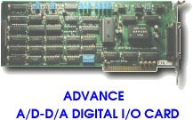
A/D-D/A digital I/O card (called advence card) is a high precision
data conversion/acquisition system for PC/XT, PC/AT, PC/386,
or compatibles. It contains two digital to analog channels with
unipolar or bipolar format,eight differential analog to digital
channels or sixteen single end analog to digital channels conversion
with unipolar or bipolar format, and two digital I/O channels with 8
bits line for each channel. |
The features of
the advance card are: |
| D/A: |
|
|
-Resolution:
12 bits.
-Output Channel:
two. (one standard, one optional)
-Output Voltage
Setting:
unipolar or bipolar selectable.
1. unipolar output: 0V
to 10V.
2. bipolar output: -10V to
10V
-Conversion time:
lusec.
-Accuracy:
1. linearity error:
+/- 0.25LSB
2. differential linearity error:
+/- 0.5LSB
3. quantizing error:
+/- 0.5LSB |
| A/D: |
|
|
-Resolution:
12 bits.
-Number of
channels:
16 or 8.
-Input Type:
1. single end mode -
16 channels.
2. differential mode - 8
channels.
-Maximum
Throughput:
25KHZ.
-Input Voltage
Range:
unipolar or bipolar selectable.
1. unipolar input: 0V
to 10V.
2. bipolar input: -10V to
10V.
-Conversion Time:
40usec.
-Channel
Acquisition Time:
2usec.
-Accuracy:
1. nonlinearity:
+/- 1LSB.
2. differential nonlinearity:
+/- 1LSB.
|
| Two digital I/O
channels. |
| I/O port
address selectable. |
|
|
Hardware
Configurations
|
Before you use the advance card,
you must ensure that the port address and jumper are set correctly, the
proper settings for the advance card are described in the following:
|
|
|
|
Software Configuratons
|
|
|
|
Fullscalar
Adjustments
|
Before getting start, you must
ensure the full scalar voltage are adjusted to satisfy the computer
power.
|
D/A
Voltage Adjustment
|
1.
|
Short
JP4-2 and JP4-3
|
2.
|
Run
ADJU.EXE to selsct D/A voltage adjustment. |
3.
|
Measure output voltage: |
|
Pin
15 and Pin 24 for D/A channel 1.
Pin 2
and Pin 24 for D/A channel 2. |
| 4. |
Adjust
VR1 (for D/A channel 1) until output voltage is equal to 10V. |
|
Adjust
VR2 (for D/A channel 2) until output voltage is equal to 10V. |
|
|
A/D
Voltage Adjustment
|
1.
|
Short
JP4-2 and JP4-3. |
2.
|
Short
JP6-1 and JP6-2. |
3.
|
Short JP7-2 and JP7-3 for unipolar. |
4.
|
Input
voltage to A/D channel by power source. |
| 5. |
Run
ADJU.EXE to select A/D voltage adjustment. |
6.
|
Adjust
VR5 until digital output is 4095. |
|
We note that, if you use bipolar,
please adjust VR3 and VR4 by yourself.
|
|
|
|
|
